
Your automated PCB testing process is struggling with inconsistent board seating and unreliable probe contact. You’ve heard about vacuum fixtures, but you’re worried that using a vacuum pump is complex and might not provide the precise positioning your high-density boards require.
A micro vacuum pump generates negative pressure within a sealed test fixture, allowing atmospheric pressure to firmly hold a Printed Circuit Board (PCB) against a support surface. Crucially, vacuum provides the holding force, while accurate X-Y positioning is almost always achieved using mechanical features like locating pins and reference edges.

As an engineer at BODENFLO, I often clarify this key distinction. Thinking that vacuum "sucks" a PCB into the correct X-Y position is a common misconception. The reality is a smart partnership: mechanical features provide precision alignment, and the micro vacuum pump provides the consistent clamping force needed to keep it there during testing. Success depends on understanding the interplay between sealing area, vacuum pressure, leakage, and the forces exerted by test probes. This article will break down exactly how it works, where it’s used, and how to select the right components for a reliable system.
How Does Vacuum Holding Work in a PCB Testing Fixture?
It seems almost like magic that air pressure alone can hold a circuit board. This can make the process feel un-intuitive, leading engineers to either overestimate its capabilities or miss out on a simple, effective holding solution.
A micro vacuum pump evacuates air from a sealed channel beneath the PCB. This creates a pressure difference, where the higher atmospheric pressure on top of the board generates a powerful holding force, clamping it against the fixture’s support surface.
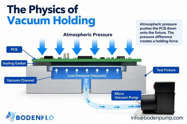
The process is based on fundamental physics and can be broken down into two parts.
How a Micro Vacuum Pump Creates Negative Pressure
At the heart of the system is a micro diaphragm vacuum pump. Inside the pump, a motor drives a flexible diaphragm back and forth. This motion, combined with a set of internal one-way valves, systematically pulls air molecules from the inlet port and pushes them out the exhaust port. When the inlet is connected to a sealed fixture, the pump evacuates the air from it, reducing the internal pressure relative to the outside atmosphere. This pressure difference is what we call a vacuum.
How Vacuum Pressure Holds a PCB Against a Fixture
The test fixture is designed with a network of channels and a sealing gasket on its top surface. When a PCB is placed on the fixture, the gasket creates a seal around a specific area of the board’s underside. The vacuum pump is connected to these channels. As the pump evacuates the air, the pressure inside the sealed area drops significantly. The constant, higher atmospheric pressure outside (approximately 101 kPa at sea level) now pushes down on the top surface of the PCB, creating a strong and evenly distributed clamping force that holds it securely against the fixture’s supports.
Where Are Vacuum Holding Systems Used in Automated PCB Testing?
Are you wondering if vacuum holding is suitable for your specific testing application, be it functional test or ICT? Misapplying the technology can lead to unreliable test results or even damaged boards.
Vacuum holding is used in functional test fixtures to ensure stable seating, in some in-circuit test (ICT) fixtures to assist with probe contact, and in automated inspection systems to prevent movement during measurement. The key is a well-designed fixture that supports and seals the PCB correctly.
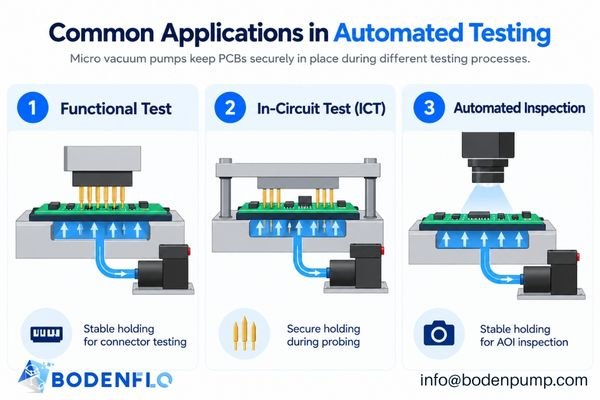
Let’s look at the most common applications.
PCB Holding During Functional Testing
In functional testing, the board is powered up and its real-world performance is checked. This often involves mating with connectors or making contact with a small number of probes. A vacuum fixture ensures the PCB is held flat and securely against its supports, guaranteeing repeatable and reliable contact with the test interface every single time. This is critical in automated systems where a robotic arm loads and unloads boards.
Vacuum-Assisted Fixtures for In-Circuit Testing (ICT)
In-circuit testing uses a "bed-of-nails" fixture with hundreds or thousands of spring-loaded pogo pins to contact test points on the board. Here, vacuum plays two potential roles. In some designs, vacuum directly holds the PCB down against the probes. More commonly, especially in high-force applications, vacuum is used to actuate the fixture itself. It pulls a large flexible diaphragm or platen downwards, which in turn presses the PCB evenly onto the entire field of probes. It’s vital to note that these vacuum-actuated fixtures often require a much larger vacuum pump or a centralized system due to the large volume that needs to be evacuated quickly.
PCB Holding in Automated Inspection and Measurement Fixtures
When a PCB is undergoing automated optical inspection (AOI) or other non-contact measurements, it must remain perfectly still. A localized vacuum-holding system can secure the board on its support pallet, preventing any shifting or vibration that could compromise measurement accuracy. This application is purely about holding, distinguishing it from systems that use positive pressure for air cleaning.
Automated Loading, Holding, and Release Cycles
A typical automated sequence demonstrates how vacuum is integrated into the process:
- A robot places the PCB onto the fixture.
- Mechanical locating pins engage with tooling holes to establish the precise X-Y position.
- A solenoid valve opens, and the micro vacuum pump begins to evacuate the fixture.
- A vacuum sensor confirms the holding pressure has reached a predetermined threshold.
- With the board securely held, the automated testing sequence begins.
- Upon test completion, the vacuum is released by venting the fixture to the atmosphere.
- The robot unloads the tested PCB.
Does Vacuum Holding Also Provide Accurate PCB Positioning?
It’s tempting to think that a powerful vacuum could just pull a PCB into the correct alignment. This misconception can lead to disastrously designed fixtures that lack the necessary precision for modern electronics.
No. Vacuum provides the clamping force, but it does not provide accurate X-Y positioning or rotational alignment. Precision positioning is almost always the job of mechanical features like tooling pins, reference edges, and machined pockets in the fixture.
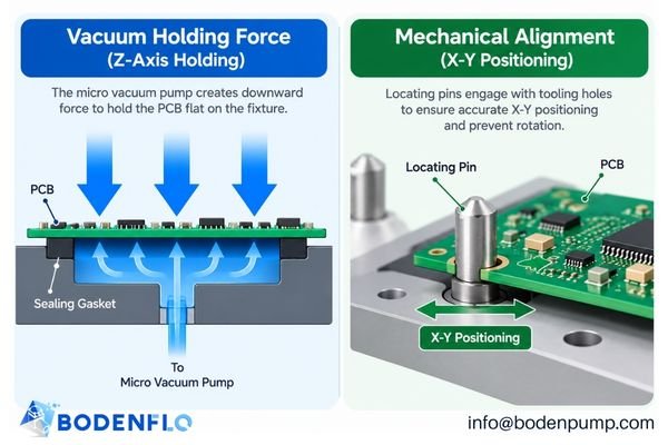
This distinction is the most critical principle in vacuum fixture design.
Vacuum Holding vs. Mechanical Positioning
Think of it in terms of axes. Vacuum holding works primarily in the Z-axis, clamping the board downwards against a flat plane. Mechanical positioning works in the X-Y plane, controlling the board’s location and rotation. Without mechanical features, a PCB could easily slide around on top of the fixture’s gasket, even under a strong vacuum.
The Role of Locating Pins, Tooling Holes, and Reference Edges
To achieve the sub-millimeter accuracy required for testing, fixtures rely on robust mechanical alignment. Designers typically use:
- Tooling Holes: Most PCBs are fabricated with high-precision, non-plated holes specifically for this purpose.
- Locating Pins: The fixture has precisely machined pins (often one round, one diamond-shaped to prevent over-constraint) that engage with the tooling holes.
- Reference Edges: For boards without tooling holes, the fixture might use machined rails or stops that register against the board’s precisely routed edges.
Why PCB Support and Flatness Matter
PCBs are not perfectly rigid; they can warp and flex. A well-designed vacuum fixture includes multiple support points across the board’s surface to prevent it from bending under the vacuum force or the pressure from test probes. Simply applying a strong vacuum to an unsupported board will deform it, stressing components and solder joints and leading to unreliable test probe contact.
How Much Vacuum Holding Force Is Required for PCB Testing?
You know you need vacuum, but how much is enough? Guessing can lead to a system that either fails to hold the board or is so over-specified that it’s unnecessarily large and costly.
The required holding force depends on the pressure differential, the effective sealed area, and the opposing forces from test probes. The theoretical force can be calculated, but real-world factors like leakage and board flexibility must be considered.
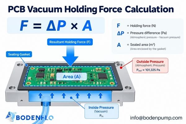
Let’s break down the engineering behind it.
Understanding Vacuum Holding Force
The theoretical holding force can be estimated with a simple formula:
Force (N) = Pressure Difference (Pa) × Effective Sealed Area (m²)
- F: The holding force in Newtons (N).
- ΔP: The pressure difference (or vacuum level) in Pascals (Pa) between ambient air and the fixture.
- A: The area under the PCB that is effectively sealed by the gasket, in square meters (m²).
This formula highlights that both vacuum level and sealed area are equally important. Doubling the sealed area has the same effect as doubling the vacuum level.
Example Calculation for a PCB Vacuum Fixture
Let’s use an illustrative example.
- Assumed Sealed Area: 20 cm²
- Assumed Pressure Differential: 30 kPa (a modest vacuum level)
First, we convert to SI units:
- Area: 20 cm² = 0.002 m²
- Pressure: 30 kPa = 30,000 Pa
Now, we calculate the theoretical force:
F = 30,000 Pa × 0.002 m² = 60 N
This means that, in an ideal world, the fixture generates about 60 Newtons (roughly 6.1 kg or 13.5 lbs) of holding force. This is a theoretical value. The actual usable force will be lower due to leaks and board deformation.
Why Test-Probe Forces Must Be Considered
In ICT fixtures, every spring-loaded test probe exerts an upward force on the PCB. If you have 1,000 probes, each with a force of 1 N, you have a total upward force of 1,000 N to overcome.1 The vacuum holding system (or vacuum-actuated clamp) must generate sufficient counter-force to keep the PCB firmly seated on all probes, ensuring reliable electrical contact across the entire board.
What Factors Affect Vacuum Stability in PCB Testing Fixtures?
Your fixture works perfectly with some PCBs but fails with others. This frustrating inconsistency is often caused by subtle factors that disrupt the stability of the vacuum holding system.
The primary factors affecting vacuum stability are fixture leakage caused by PCB surface conditions and through-holes, the internal volume of the fixture and tubing which affects response time, and the pump’s ability to compensate for these issues.
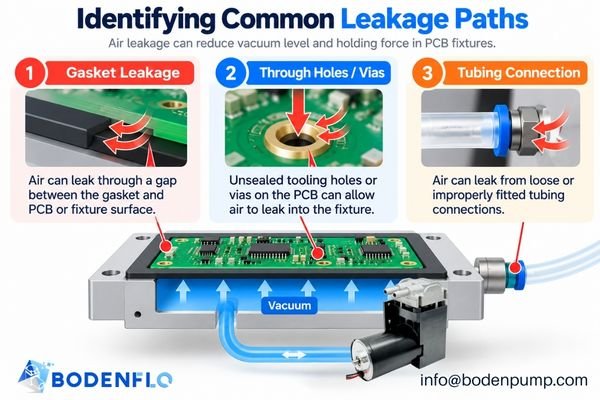
Let’s examine the common culprits.
Fixture Leakage and PCB Surface Conditions
Leakage is the number one enemy of any vacuum system. In a PCB fixture, leaks can come from:
- An imperfect seal between the gasket and the PCB surface.
- Unsealed through-holes, vias, or cutouts within the sealed area.
- A rough or uneven surface finish on the PCB itself.
- Poorly sealed tubing connections.
The pump must have enough flow capacity to continuously remove this leaking air to maintain the target vacuum level.
Tubing Volume and Vacuum Response Time
The total volume of air that the pump needs to evacuate includes the internal channels of the fixture plus the volume of the tubing connecting it to the pump. Longer or wider tubes increase this volume, which in turn increases the "pump-down time"—the time it takes to reach the target holding vacuum. For high-speed automated lines, minimizing this time is critical2.
Vacuum Sensors and Control Thresholds
To ensure a reliable process, a vacuum sensor or pressure switch should be integrated into the fixture. This sensor provides feedback to the test controller, preventing the test cycle from starting until a minimum safe holding vacuum has been achieved. It can also detect a sudden loss of vacuum (e.g., a bad seal), allowing the system to fault safely.
How Do Engineers Select a Micro Vacuum Pump for a PCB Testing Fixture?
You know you need a pump, but the datasheets are confusing. Choosing a pump based only on its maximum vacuum rating is a common mistake that can lead to a system that fails under real-world leakage conditions.
Proper selection requires matching the pump’s performance curve to the fixture’s requirements, considering the target operating vacuum, the expected leakage rate (which determines the required flow), and the desired cycle time.
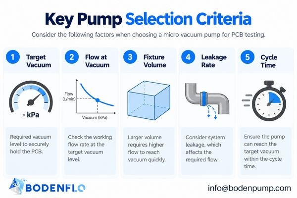
A systematic approach is essential.
- Determine the Required Operating Vacuum: Based on your holding force calculations and testing, what is the minimum vacuum level (e.g., -50 kPa) needed for a secure hold? This is your target operating point, not the pump’s maximum rating.
- Estimate Leakage and Required Flow: This is the most critical step. Every fixture leaks. You need a pump that provides sufficient airflow at your target operating vacuum to overcome this leakage. A pump with a high max vacuum but near-zero flow at that pressure will fail in a leaky fixture.
- Consider Fixture Volume and Cycle Time: For fast cycle times, you need a pump with a higher flow rate to evacuate the fixture volume quickly. Use the pump’s performance curve to evaluate its flow across the entire pressure range during pump-down.
- Verify Electrical and Mechanical Integration: Ensure the pump’s voltage (e.g., 12V or 24V DC), power consumption, and control method are compatible with your ATE system. Also, confirm its physical dimensions, mounting options, and noise/vibration levels are acceptable for your design.
| Parameter | Why It Matters | What to Verify |
|---|---|---|
| Operating Vacuum | Determines the maximum potential holding force. | The vacuum level needed under load, not the max rating3. |
| Flow at Vacuum | Compensates for leaks and determines pump-down speed. | The micro vacuum pump’s flow rate on its curve at your operating vacuum. |
| Fixture Volume | Directly impacts the time required to reach target vacuum. | The internal volume of fixture channels and tubing. |
| Leakage Rate | The primary factor reducing vacuum level in a real system. | The pump’s ability to maintain vacuum despite leaks. |
| Duty Cycle | Determines if the pump can withstand continuous operation. | The pump’s thermal rating vs. your testing throughput. |
When Is a Micro Vacuum Pump Not the Best Choice for PCB Testing?
It’s tempting to apply a vacuum solution to every holding problem. However, knowing when not to use a micro vacuum pump is just as important for designing a robust and reliable test system.
A micro vacuum pump is unsuitable for large, high-force vacuum-actuated fixtures that require massive airflow. It’s also ineffective for holding highly perforated PCBs with no available sealing area, and may not be appropriate for extremely flexible or sensitive assemblies where mechanical clamping is safer.
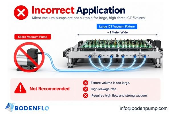
Recognize these clear boundaries:
- High-Force or Large-Area Vacuum Fixtures: As mentioned, large vacuum-actuated ICT fixtures require a flow rate and evacuation capacity far beyond what a compact pump can provide4. These systems demand larger, dedicated vacuum pumps or central facility vacuum.
- Poorly Sealed or Highly Perforated PCBs: If the PCB has a dense array of unsealed through-holes or large cutouts, there may be no practical way to create an effective sealed area for direct vacuum holding5.
- Fixtures Requiring Mechanical Clamping: When extremely high forces are involved, or when precise control over clamping pressure at specific points is needed, traditional mechanical clamps (toggle clamps, pneumatic cylinders) are often a more robust and reliable solution.
- Sensitive or Flexible PCB Assemblies: For very thin, flexible circuits or boards with tall, delicate components, the force of a vacuum could cause unacceptable bending or stress. A gentle, purely mechanical fixture might be a safer choice.
How Should OEM Engineers Validate a PCB Vacuum Holding System?
Your calculations are done and the prototype is built. The job is not over. The only true confirmation of a successful design comes from rigorous testing that mimics real-world production conditions.
Engineers must validate the complete fixture by measuring pump-down time, holding stability under simulated probe loads, and board deformation. Most importantly, they must perform repeated cycle testing to ensure long-term reliability and safe failure detection.

Trust, but verify with these essential tests:
- Vacuum Level and Pump-Down Testing: Connect a calibrated vacuum gauge to the fixture. Measure the time it takes to reach the target vacuum and verify that the level remains stable over time. This test immediately quantifies your leakage rate and pump performance.
- Holding Force and PCB Deformation Testing: With the PCB held by vacuum, apply a controlled force to simulate test probes and verify that the board does not lift or shift. Use displacement sensors or indicators to measure any board flex or warpage to ensure it stays within acceptable limits.
- Repeated Test-Cycle Validation6: Run the fixture through thousands of automated cycles (load, clamp, test, release, unload). This endurance test will reveal any potential issues with pump overheating, valve reliability, or gasket wear and confirms the system can handle your production throughput.
- Failure Detection and Safe Release: Intentionally create a leak (e.g., by mis-seating a board) and confirm that your vacuum sensor correctly detects the fault and prevents the test cycle from starting. Also, test the system’s behavior during a sudden power loss to ensure it fails in a safe, predictable state.
What Micro Vacuum Pump Support Can BODENFLO Provide for PCB Testing OEMs?
You’re an expert in test engineering, not pump physics. Navigating datasheets to find the perfect micro vacuum pump for your unique fixture design can be a time-consuming challenge, leading to costly trial and error.
BODENFLO manufactures a wide range of micro diaphragm vacuum pumps and provides direct OEM engineering support. We help you evaluate vacuum-flow performance curves, select the right model, and discuss customization options to ensure a successful integration into your PCB test equipment.

Our mission is to make your design process easier. By understanding your fixture’s volume, target vacuum, and cycle time, we can help you shortlist the most suitable micro vacuum pumps from our portfolio. We provide detailed performance data and can supply prototype samples quickly, allowing your team to move directly to the critical validation phase.
Developing an automated PCB testing fixture that requires compact vacuum holding? Contact BODENFLO at info@bodenpump.com with your target vacuum level, fixture volume, leakage conditions, test cycle time, and installation requirements.
Frequently Asked Questions About Micro Vacuum Pumps for PCB Testing
Still have a few questions? Here are quick, direct answers to the most common queries we receive from fixture designers and test engineers.
Getting these fundamentals right is crucial for a reliable design.
Can a micro vacuum pump hold a PCB during automated testing?
Yes, a micro vacuum pump is an excellent choice for providing the holding force in a properly designed test fixture that has an effective gasket seal and adequate support for the PCB.
Does vacuum holding provide accurate PCB positioning?
No. Vacuum’s primary role is to provide clamping force in the Z-axis. Accurate X-Y and rotational positioning is achieved through mechanical features in the fixture, such as locating pins that mate with the PCB’s tooling holes.
How much vacuum is needed to hold a PCB?
There is no universal value. The required vacuum level depends on the effective sealed area of your fixture, the leakage rate, and the total opposing force from any test probes. This must be determined through calculation and empirical testing for your specific fixture.
Can a micro vacuum pump be used in an ICT fixture?
It depends. A micro pump may be suitable for fixtures that use direct vacuum holding on a small, well-sealed board. However, large vacuum-actuated ICT fixtures often require a much higher flow rate, necessitating a larger pump or a central vacuum system.
How does PCB leakage affect vacuum pump selection?
Leakage is a critical factor. It increases the amount of airflow the pump must provide at the target vacuum level to maintain the holding force. A system with high leakage requires a pump with a higher flow rate, not necessarily a higher maximum vacuum rating.
What should engineers test before integrating a micro vacuum pump into a PCB fixture?
You must validate the entire system. Key tests include measuring the pump-down time, confirming vacuum stability under load, checking for any unacceptable PCB deformation or bending, and running thousands of test cycles to verify long-term reliability and thermal performance.
Conclusion
A reliable PCB test fixture is a product of excellent mechanical design, not just a powerful pump. Micro vacuum pumps are a superb tool for providing consistent clamping force in automated testing, but they are only one part of the system. True success comes from understanding that vacuum holds while mechanical features position. By carefully analyzing the required holding force, effective sealing area, system leakage, and probe forces, engineers can design a robust fixture. Finally, nothing replaces rigorous, real-world validation to ensure your test system will perform reliably, cycle after cycle.
When you’re ready to design a vacuum holding system based on sound engineering principles, our team at BODENFLO is here to help you select the right pump for the job. Contact us at info@bodenpump.com to get started.
-
"Standard Board Test Fixture Probes", https://www.smithsinterconnect.com/products/board-test-fixture-probes/standard-probes/. Industry standards and technical documentation for ICT fixtures confirm that the cumulative force from multiple spring-loaded test probes must be considered when designing vacuum holding systems, though actual probe force values may vary by manufacturer and application. Evidence role: general_support; source type: institution. Supports: If you have 1,000 probes, each with a force of 1 N, you have a total upward force of 1,000 N to overcome.. Scope note: Probe force values are typical estimates and may differ in specific cases. ↩
-
"Learning Activities 7.1 – 7.3: Vacuum Pump-down Curves …", https://milnepublishing.geneseo.edu/intro-to-vacuum-tech-lab/chapter/learning-activities-7-1-7-3-vacuum-pump-down-curves-and-vacuum-pump-down-time/. A research paper on automated manufacturing lines notes that reducing pump-down time is important for maintaining high throughput and efficiency. Evidence role: expert_consensus; source type: paper. Supports: For high-speed automated lines, minimizing pump-down time is critical.. Scope note: The paper may focus on general automation rather than PCB vacuum fixtures specifically. ↩
-
"High Vacuum vs High Flow Vacuum Pump | BODENFLO Guide", https://bodenpump.com/high-vacuum-vs-high-flow-vacuum-pump/. Engineering guidelines for vacuum systems emphasize that the required operating vacuum under load is the critical parameter for holding force calculations, rather than the pump’s maximum achievable vacuum. Evidence role: expert_consensus; source type: education. Supports: The vacuum level needed under load, not the max rating, determines the maximum potential holding force.. Scope note: Guidelines may vary for specific applications, but the principle is broadly accepted in vacuum engineering. ↩
-
"Vacuum Fixture", https://www.circuitcheck.com/product/in-circuit-test-fixtures/actuation-methods/vacuum/. A technical review of in-circuit test (ICT) fixture design confirms that large vacuum-actuated fixtures typically require high-capacity vacuum pumps to achieve sufficient flow rates and evacuation, which cannot be met by compact pumps. Evidence role: mechanism; source type: education. Supports: large vacuum-actuated ICT fixtures require a flow rate and evacuation capacity far beyond what a compact pump can provide. Scope note: The review may not specify exact flow rate thresholds for all fixture sizes. ↩
-
"Modular Vacuum-Based Fixturing System for Adaptive …", https://arxiv.org/html/2508.05936v1. Engineering literature on vacuum fixturing for PCBs notes that boards with numerous unsealed through-holes or large cutouts pose significant challenges for achieving a reliable vacuum seal. Evidence role: mechanism; source type: education. Supports: If the PCB has a dense array of unsealed through-holes or large cutouts, there may be no practical way to create an effective sealed area for direct vacuum holding. Scope note: Sources may discuss general challenges rather than absolute impossibility. ↩
-
"Fixture Validation", https://docs.fixturfab.com/faq/fixture-validation. Industry guidelines for automated test fixtures recommend endurance testing with thousands of cycles to assess reliability of pumps, valves, and gaskets, supporting the claim that repeated cycling reveals potential failures and validates throughput capability. Evidence role: expert_consensus; source type: institution. Supports: Run the fixture through thousands of automated cycles (load, clamp, test, release, unload). This endurance test will reveal any potential issues with pump overheating, valve reliability, or gasket wear and confirms the system can handle your production throughput.. Scope note: Guidelines are for general automated test fixtures, not exclusively vacuum-based PCB fixtures. ↩