Staring at a brushless diaphragm air pump with its assortment of 2, 3, 4, or even 5 wires can be daunting. If you’re wondering what each wire does, you’re not alone. Getting it wrong can mean a pump that doesn’t work, or worse.
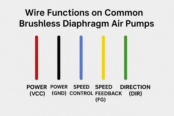
Brushless diaphragm air pump wires primarily handle Power (Positive VCC, Negative GND). Additional wires enable Speed Control (PWM or Analog), provide Speed Feedback (FG/Tachometer), and sometimes offer Direction Control (DIR). The number of wires—from 2 to 5—indicates the level of control and feedback available.
Successfully using these pumps in your project, whether it’s a medical device, a lab instrument, or a personal invention, starts with understanding these connections. I’ve worked with countless variations of these pumps, and while the wire colors can sometimes vary, the core functions are pretty standard. Let’s break down what each wire configuration typically offers, helping you get your pump up and running smoothly.
What Can You Expect From a Simple 2-Wire Brushless Air Pump Setup?
You’ve got a brushless air pump with just two wires. This is the most basic configuration. What does this simplicity mean for its operation and your ability to control it?
A 2-wire brushless air pump usually only provides Power Positive (often Red) and Power Negative (often Black). These pumps are designed to run at a fixed, internally set speed once the correct DC voltage is applied, offering no external speed adjustment.
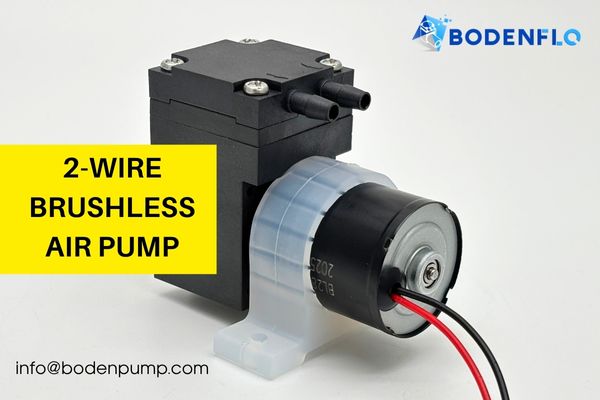
In my experience building various systems, these 2-wire pumps1 are the go-to choice for applications needing straightforward, continuous operation. Think of simple aeration tasks or situations where a constant, non-adjustable flow or pressure is perfectly adequate. The beauty of these pumps lies in their "plug-and-play" nature. You connect power, and they do their job. The internal brushless motor driver2 handles all the commutation (the process of switching power to the motor coils in sequence) automatically. There’s no need for you to worry about complex control signals. However, this also means you give up any ability to fine-tune its performance externally. Always double-check the pump’s datasheet for the precise operating voltage3 (e.g., 12VDC or 24VDC). Supplying the wrong voltage is one of the quickest ways I’ve seen these pumps get damaged.
| Wire Color (Common) | Function | Typical Voltage | Key Considerations for You |
|---|---|---|---|
| Red | Power Positive | e.g., 12V or 24V DC | Must match pump’s specification. Connect to V+ of your supply. |
| Black | Power Negative | GND | Common ground. Connect to V- or GND of your power supply. |
How Does a Third Wire Typically Enhance Brushless Air Pump Control?
When your brushless air pump sports a third wire, it almost invariably signals an upgrade in control capability. What new function does this extra wire usually bring to the table?
With a 3-wire brushless air pump, you generally get Power Positive, Power Negative, and a dedicated Speed Control input (often a Blue or White wire). This crucial third wire allows you to dynamically adjust the pump’s operating speed.
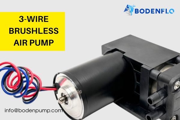
This speed control feature is a game-changer for many applications. I’ve integrated these into projects ranging from precise gas sampling systems to medical devices requiring variable airflow. The ability to modulate the speed allows you to optimize flow rates, reduce operational noise when full power isn’t needed, and even conserve energy. Typically, speed is controlled in one of two ways via this third wire:
- PWM (Pulse Width Modulation) Input4: You supply a square wave signal. The duty cycle (the percentage of time the signal is high versus low) dictates the speed. A low duty cycle means low speed, and a high duty cycle means high speed. Datasheets will specify the required PWM frequency (e.g., 15kHz – 25kHz) and voltage amplitude (e.g., 5V). One of your examples mentioned a Blue wire for this.
- Analog Voltage Input5: You supply a variable DC voltage, often in the range of 0-5V or, as in one of your provided examples, 0.5V-4.5V using a Blue wire. The pump speed changes proportionally to this voltage level.
It’s also interesting to note, as per your input, that some pumps with a Blue speed control wire6 might default to full speed if this wire is shorted to VCC (Power Positive) or possibly if left disconnected (due to an internal pull-up resistor). Always check the manufacturer’s documentation for such specific behaviors. This means if you don’t need speed control, you might be able to run it at max speed without an external signal.
| Wire Color (Example) | Function | Input Type for Speed Control | Typical Range (from your example) |
|---|---|---|---|
| Red | Power Positive | – | e.g., 8-24VDC |
| Black | Power Negative | – | GND |
| Blue ("SP") | Speed Control | PWM or Analog Voltage | PWM: 15-25kHz, 5V, 0-100% duty |
| Analog: 0.5V – 4.5V DC |
What Advanced Features Do 4-Wire and 5-Wire Brushless Air Pumps Offer?
Moving up to 4 or 5 wires on your brushless air pump unlocks even more sophisticated control and monitoring. What are these additional wires typically used for?
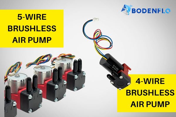
4-wire pumps often introduce either a Speed Feedback (FG/Tachometer) output or a Direction Control (DIR) input, alongside power and speed control. 5-wire pumps usually provide the full suite: Power, Speed Control, Speed Feedback (FG), AND Direction Control (DIR).
These more comprehensive wiring schemes are invaluable in applications demanding precision, closed-loop control, system diagnostics, or bi-directional motor operation (though actual flow reversal in diaphragm pumps is rare unless specifically designed). I’ve found the FG signal particularly useful for confirming pump operation and maintaining consistent performance under varying loads.
Let’s look at what these extra signals mean, based on your provided examples:
-
Speed Feedback (FG – Frequency Generator / Tachometer)7:
- This wire (e.g., a Yellow or Green wire in your examples) outputs a series of pulses. The frequency of these pulses is directly proportional to the pump motor’s actual rotational speed.
- This is incredibly useful. By counting these pulses, your microcontroller can calculate the RPM, enabling you to implement closed-loop speed control (where the system actively adjusts the PWM to maintain a target speed) or to detect if the pump has stalled or is struggling. One of your examples states the Yellow FG wire "outputs one pulse per motor revolution."
- Often, if you don’t need this feedback, the FG wire can be "left floating" (disconnected), as noted for a Green FG wire in another example.
-
Direction Control (DIR / CW/CCW)8:
- This input wire (e.g., a Green or Yellow wire in your examples) allows you to set the rotational direction of the brushless motor inside the pump. It’s typically a simple high/low logic signal.
- For most standard diaphragm air pumps, changing the motor’s rotation direction does not reverse the direction of airflow due to the mechanics of the diaphragm and valves. However, this feature might be present because the underlying brushless motor controller supports it, or for very specialized pump designs.
- If direction control isn’t needed, this wire can often be "left floating," as mentioned in your examples for both Green and Yellow direction wires, causing the pump to run in a default direction.
A 4-wire setup might combine Power, Speed Control (PWM/Analog), and an FG output. For instance: Red (VCC), Black (GND), Blue (Speed Control), Yellow (FG).
A 5-wire setup, like one of your examples (Red: 12V+, Black: 12V-, Blue: PWM, Green: FG, Yellow: DIR), gives you the most complete interface. It’s vital to remember that wire colors like Green and Yellow can be used for either FG or DIR by different manufacturers, so the datasheet is your ultimate guide!
| Wire Color (Common in Your Examples) | Function | Notes from Your Examples |
|---|---|---|
| Red | Power Positive | e.g., 12V or 24V DC |
| Black | Power Negative | GND |
| White / Blue | Speed Control | PWM input. Blue also for Analog Voltage in one example. |
| Green / Yellow | Speed Feedback (FG) | Outputs pulses proportional to speed. Can often be left floating. |
| Green / Yellow | Direction (DIR) | Sets motor direction. Can often be left floating for default. |
Where Are These Versatile Brushless Diaphragm Air Pumps Commonly Used?
Knowing the wire functions is great, but where do these brushless diaphragm air pumps actually find their niche? Their reliability and controllability open up a wide range of applications.
Brushless diaphragm air pumps are widely used in medical devices (like gas analyzers, NPWT), environmental monitoring (air samplers), laboratory equipment (vacuum filtration, fluid dosing), and even consumer products (aquarium aeration, aroma diffusers), with wire count often matching application complexity.

I’ve seen these pumps perform reliably in so many different fields. Their brushless nature means longer life and less maintenance than brushed counterparts, which is critical in many professional settings.
-
Medical Devices: This is a huge area. You’ll find them in:
- Gas sampling and analysis: For drawing air/gas samples into sensors (e.g., capnography, anesthesia monitors). Here, precise speed control (3 or 4-wire) is often essential.
- Negative Pressure Wound Therapy (NPWT)9: Creating a controlled vacuum to promote healing. FG feedback (4 or 5-wire) can be crucial for ensuring consistent therapy.
- Blood pressure monitors: Inflating cuffs.
- Nebulizers and aspirators: Requiring controlled air pressure/flow.
-
Environmental Monitoring:
- Portable air samplers: Drawing air through filters for particulate or chemical analysis. Battery life (efficient speed control) and reliability are key.
- Gas detection systems10: Pulling ambient air across sensors.
-
Laboratory and Analytical Instruments:
- Vacuum filtration: Pulling liquids through filter media.
- Microfluidics and liquid handling11: Precise, low-volume fluid movement. Speed control is paramount.
- Automated pipetting systems.
-
Consumer and General Industrial Products:
- Aquarium aeration: Simple 2-wire pumps are often sufficient here.
- Aroma diffusers and air fresheners.
- Printing equipment: For paper handling or ink supply.
- Small robotic applications: Pneumatic gripping or actuation.
The choice of a 2, 3, 4, or 5-wire pump often depends on the level of precision and feedback the application demands. A simple "always on" task might use a 2-wire pump, while a critical medical device needing precise flow and safety monitoring would opt for a 4 or 5-wire version.
Do You Have More Questions About Brushless Air Pump Wiring?
Even with the explanations, some specific questions often pop up when you’re about to connect your pump. Let’s tackle a few common ones I’ve encountered.
Common questions involve dealing with incorrect connections, PWM signal compatibility with pump voltage, achieving closed-loop control without FG, variations in wire colors, and the need for external components like pull-up resistors.

Here are some frequently asked questions that might help you avoid common pitfalls:
- Q: What happens if I accidentally reverse the Power Positive and Power Negative wires?
A: In most cases, this is bad news. You could damage the pump’s internal driver electronics permanently. Some pumps might have reverse polarity protection, but it’s not guaranteed. I always say: double-check your power connections before applying power! - Q: My pump is 24V, but my microcontroller outputs a 3.3V or 5V PWM signal. Is that okay for the speed control wire?
A: Usually, yes. The speed control input (PWM or analog) is often designed to accept standard logic level signals (e.g., 0-5V). The pump’s main operating voltage (12V or 24V) is separate from the signal voltage level for control lines. However, always verify this in the pump’s datasheet. The datasheet will specify the acceptable voltage range and type for the control inputs. - Q: If my 3-wire pump only has a speed control input (no FG wire), can I still achieve accurate closed-loop speed control?
A: It’s much harder. Without direct speed feedback (FG), you’re operating in an open-loop manner. You can command a speed, but you won’t know if the pump is actually achieving it, especially if the load changes. For true closed-loop control, you’d need to add an external sensor to measure flow or pressure, which adds complexity. - Q: The datasheet for my pump lists slightly different wire colors than your examples, or the colors seem ambiguous. What should I do?
A: Prioritize the pin numbers or explicit function descriptions in the datasheet over generic color assumptions. While colors are often standard, manufacturing variations or different product lines can lead to differences. If a datasheet is available, it is your definitive guide. Sometimes, contacting the manufacturer or supplier is the best way to resolve ambiguity. - Q: Do I need to add external pull-up or pull-down resistors for the FG or DIR signal lines?
A: It depends on the output type of the FG signal and the input type of the DIR signal, as well as what your microcontroller expects. FG signals are often "open-collector" or "open-drain," which do require an external pull-up resistor to your microcontroller’s logic voltage. DIR inputs might have internal pull-ups/pull-downs (as implied by "can be left floating"). Again, the pump’s datasheet is the best source for this information.
Conclusion
From simple 2-wire operation to sophisticated 5-wire control and feedback, understanding your brushless diaphragm air pump’s wiring is essential. Power, Speed Control (PWM/Analog), Speed Feedback (FG), and Direction (DIR) are the key functions. Armed with this knowledge and your pump’s datasheet, you can confidently integrate these versatile devices into a multitude of applications.
-
Explore the benefits of 2-wire pumps to understand why they are ideal for continuous operation and simple tasks. ↩
-
Learn about brushless motor drivers to see how they enhance pump efficiency and reliability in various applications. ↩
-
Understanding the significance of operating voltage can help prevent damage and ensure optimal pump functionality. ↩
-
Understanding PWM is crucial for optimizing speed control in various applications. Explore this link to deepen your knowledge. ↩
-
Learn about Analog Voltage Input to enhance your projects with effective speed modulation techniques. This resource will be invaluable. ↩
-
Discover the role of the Blue speed control wire in pump systems to ensure efficient operation and control. This information is essential for your projects. ↩
-
Understanding Speed Feedback is crucial for implementing effective closed-loop control in motor systems, enhancing performance and reliability. ↩
-
Exploring Direction Control mechanisms can help you optimize motor performance and understand airflow dynamics in pumps. ↩
-
Explore this link to understand how NPWT promotes healing through controlled vacuum, a critical application in medical devices. ↩
-
Learn about gas detection systems to see their importance in safety and environmental monitoring, crucial for various industries. ↩
-
Discover the role of microfluidics in precise fluid movement, essential for advancements in laboratory and analytical instruments. ↩